This article goes through how to replace a SC0-SC2 spindle speed magnet if it is damaged or loose
Spindle magnet replacement
Summary
This article provides an overview on how to change out a faulty speed magnet.
Tool list
|
C-Spanner
|
|
|
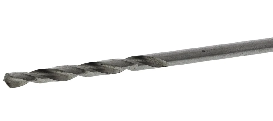
3.2mm Drill Bit
|
|
|
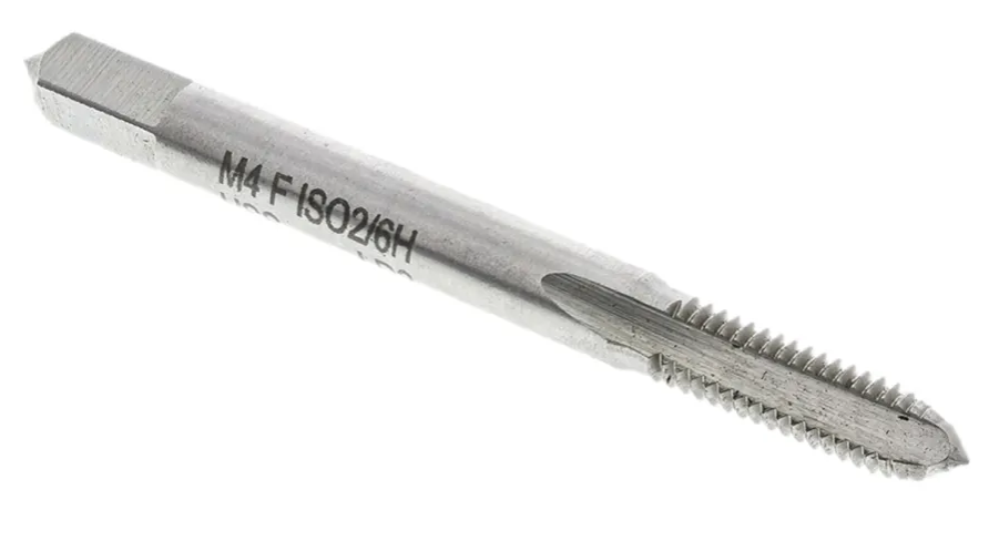
M4 Tap
|
|
|
Green loctite - 648
|

|
|
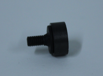
Speed magnet
|
|
Disassembly
Step 1 - loosening the rotor nut
Use the C-Spanner to loosen the rotor nut. If it’s so tight that it can't be undone by hand you can carefully secure the bearing housing within a vice, be careful not to crush the bearings or the bearing housing.
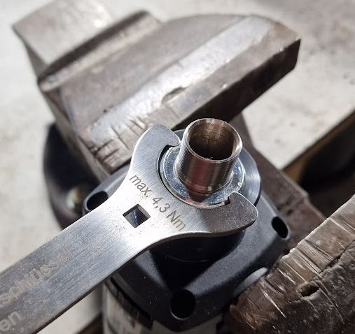
Step 1a - Turning the rotor nut
This should allow for you to have more leverage onto the C-Spanner which should undo the nut but only to loosen it.

Step 2 - Removing the rear cover
Remove the rear cover using a T-20 Torx screwdriver on the singular screw and begin to unscrew it. This should then allow the back cover to slide off exposing the PCB and brushes.
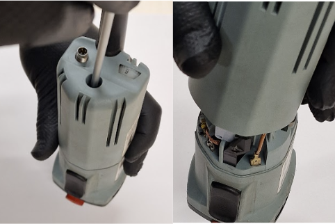
If present, remove captive nut from speed control port using 10mm nut driver (This may not be present on newer spindles)

Step 3 - Removing the motor brushes
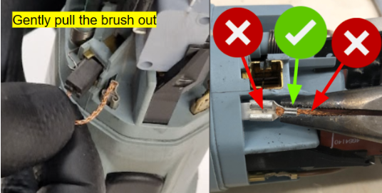
To remove the motor brushes, carefully pull them out by grabbing onto the cable and fully removing them from the brush holder. Once this has been done carefully pull the crimp off using needle nose pliers.
|

|
Put the brushes to the side in a safe place because they will need to be reused when the assembly procedure happens.
|
Step 4 - Remove the bearing housing
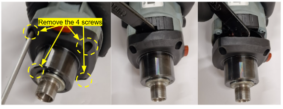
Remove the 4 T-20 Torx screws in the bearing housing shown below. Once this has been done using the back of the collet spanner, wedge it inside the vent and it should allow the rotor assembly to be popped out from its seated location and allow it to be removed. This may be tight and requires some force to separate.
Step 5 - Undo the rotor nut
Once the rotor assembly has been removed you can now undo the rotor nut which will now allow you to remove the rotor from the bearing housing.

Step 6 Removing the Rotor
Once you have removed the rotor nut you will now be able to remove the rotor, to do this you may need to lightly hit the rotor with the rubber hammer provided, as it may be tight.
Step 7 - Remove the speed magnet
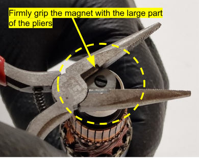
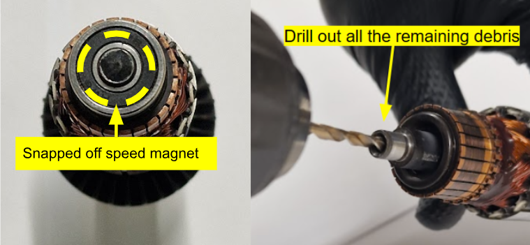
If you have a chipped but still present speed magnet you will need to remove it for replacement, if your magnet is detached you can stick this step - carefully start unscrewing it using a pair of needle nosed pliers as shown below. If the speed magnet shears off do not worry as further along you will need to re-drill and tap the thread for the magnet.
Step 8 - Preparation for speed magnet installation
If necessary using a 3.2 mm drill bit, drill out the remaining plastic for the speed magnet from inside the rotor .
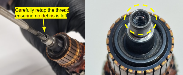
Re-tap the thread for the speed magnet using a M4 Tap, This will clear up the threads and allow for the new speed magnet to sit correctly.
Assembly
Step 9 - Rotor assembly
Open the new speed magnet and apply a small amount of green loctite to the thread before installing, hand tighten into the tail bearing thread to make sure the thread doesn't get damaged from being over tightened.

Step 10 - Installation of the assembly housing
Install the assembly housing over the rotor but not forgetting the steel spacer between the assembly housing and the bearing housing.
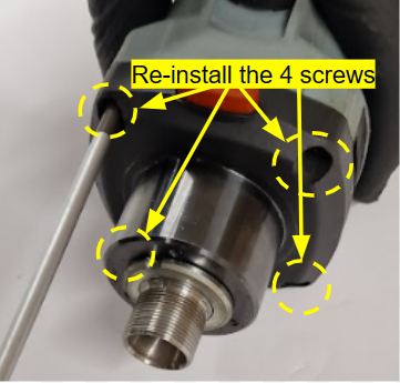
Reinstall the 4 Torx screws back into the bearing housing using the T-20 Torx driver provided
Step 11 - Finish installing the rotor
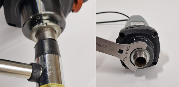
Lightly knock the threads of the collet with a rubber mallet so that it sits into place and then proceed to hand tighten the rotor nut using the C-spanner.
This will evenly pull everything together and reduce the amount of load on the bearings.
Step 12 - Reinstalling the brushes
Reinstall the brushes into the motor as shown below but be careful of not damaging the cables. If the crimps are visibly loose, you can use pliers to close them over slightly to ensure a tighter fit.

Step 13 - Reattach the rear casing
Install the rear case back over the rotor but ensure not to crush any of the loose cables.Once this has been seated correctly you may now screw the last T-20 torx screw to finish the assembly procedure.
