.
Initial diagnosis
Use the test procedure to evaluate if the spindle can be turned on by SmartBench or not.
If the spindle turns on during this procedure, but not during a job, then the problem is with the job file, not the spindle. Check that the job file has the spindle speed set to over 5000 rpm, anything lower will cause issues.
If the spindle does not turn on using the test procedure, continue reading.
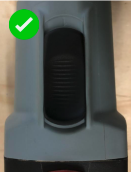
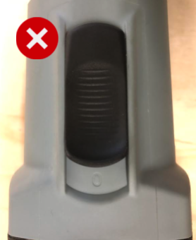
Check that the spindle switch is on
The spindle for safety reasons has an on/off slider on the side. Check this is on.
Check the spindle brushes condition, length, wire position and casing
Check the condition of the spindle brushes.
Check that the brushes are still over 9.5 mm long (illustrated here).
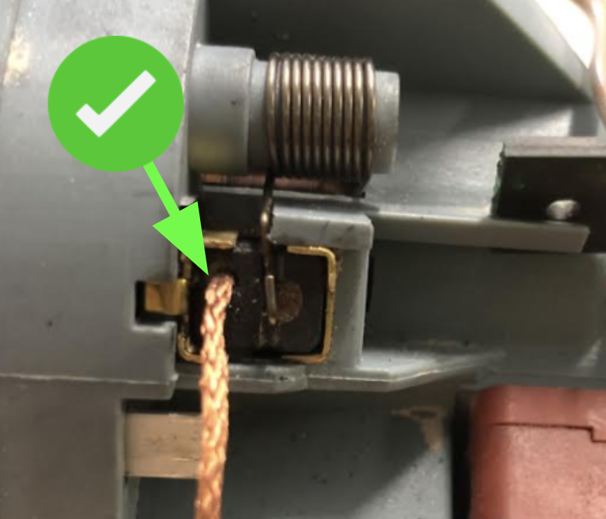
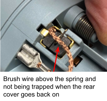
With the rear cover off also check that the brush wire is installed on the correct side furthest from the PCB - see this link for further reference. Make sure the brush wire is above the retaining spring and not fouling on anything especially when the rear cover goes back on. Clean any dust or debris from inside the brush housing while they are removed. Also clean the PCB of any extra debris.
Remove IM flashing
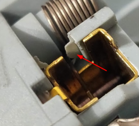
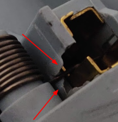
On older SC1 spindles a fault was identified which prevented the spring and the brush from moving down correctly. Using a knife, cut away an excess flashing to allow spring to move freely.
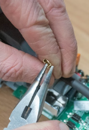
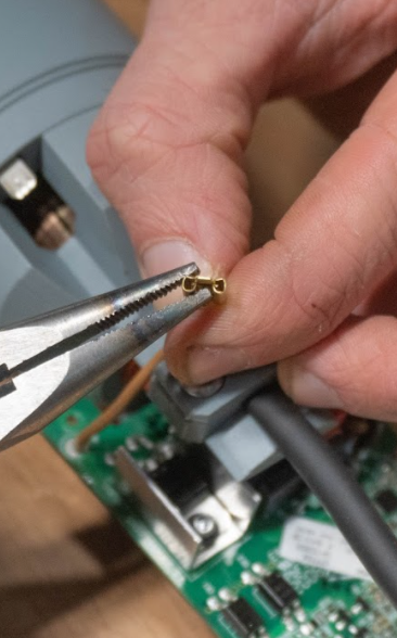
Check power crimps
Check power connection crimps (both sides).
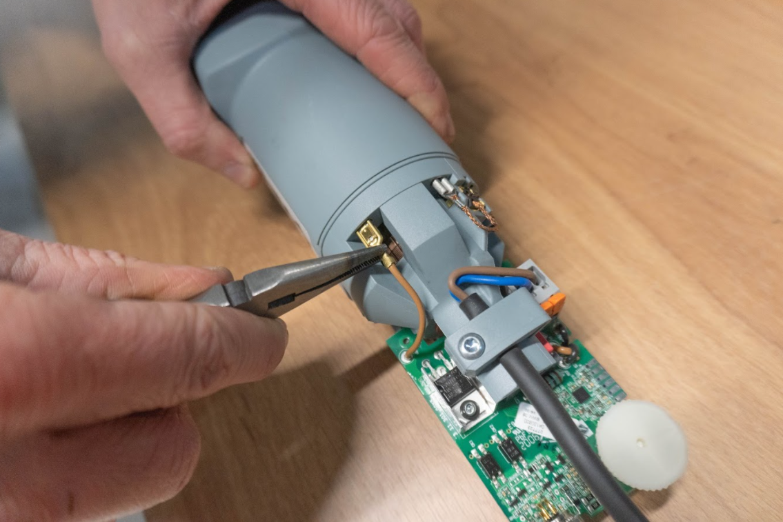
If loose, use pliers to close them over
Check the spindle in manual mode and outside of Smartbench
Please refer to this article which demonstrates how the spindle can be attempted to be run in both “Manual mode” which the speed control cable disconnected which would indicate a speed control cable fault if run correctly. And also testing the spindle outside of Smartbench to see if it correctly runs separate from Smartbenches control system.
Check the speed magnet condition
Please use this article to ensure that the speed magnet on top of the spindle rotor is still in good condition, if this is damaged or not attached the spindle PCB cannot correctly read the spindle speed when it is turned on
Multimeter checks
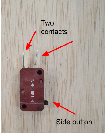
Check the switch visually for continuity
With a multimeter check the switch used for turning the spindle on is still in good condition. When the switch is clicked on with the button on the side the two contacts in good condition will be continuous
Check the power cable
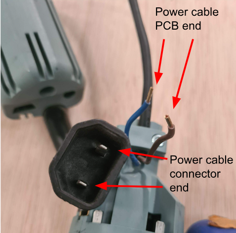
If you have a multimeter check the power cable for continuity for both wires, between the PCB end and the power cable connector end - these should both be continuous.
If there is a break in these wires power cannot reach the spindle
