Overview
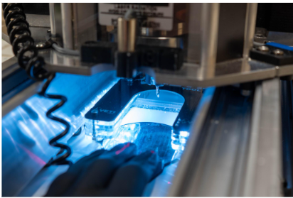
Shapes is a on-console application that allows the user to effortlessly cut simple shapes without the need for CAD/CAM software.
Shapes is the first of the YetiCut app series with a vision to make it easier than ever to use a CNC machine.
Shapes currently supports the following geometries:
-
Squares
-
Rectangles
-
Circles
-
Straight lines
How do I get Shapes?
Shapes is available to all SmartBench users, and is completely free!
Shapes is available from software version 2.9.2 and above. To check which version of software you are, please see this article here
To update your software, please see this article here.
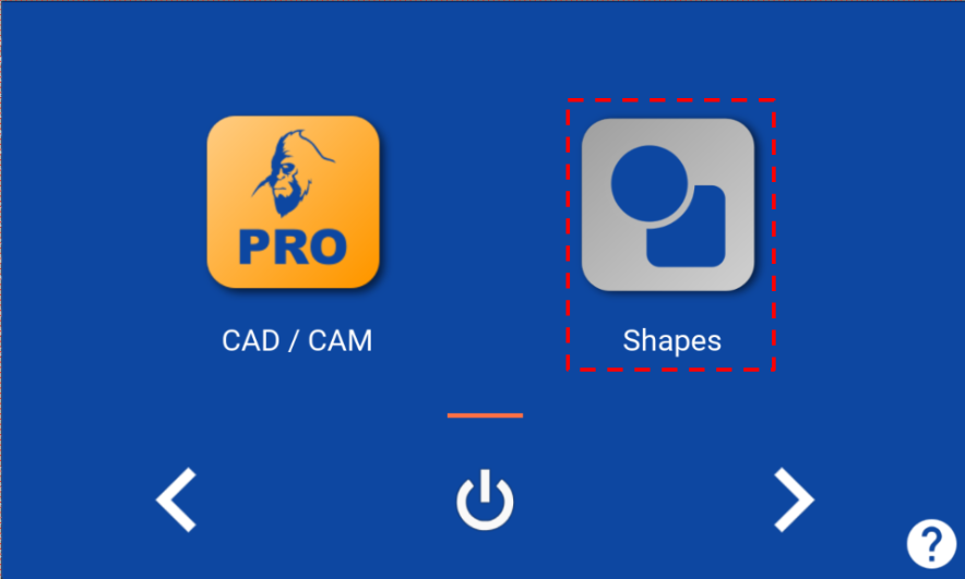
Shapes can be found in by clicking on the Shapes icon from the main lobby
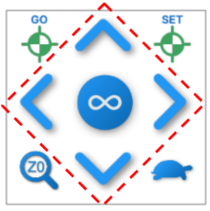
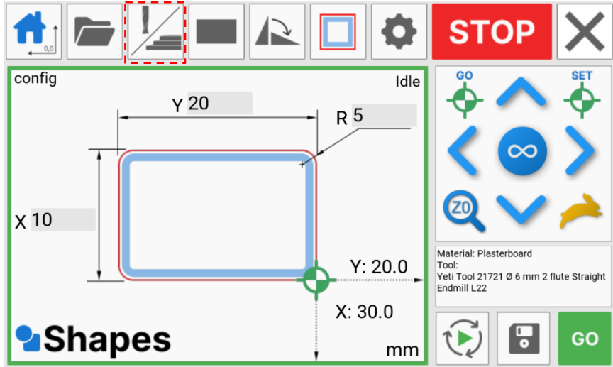
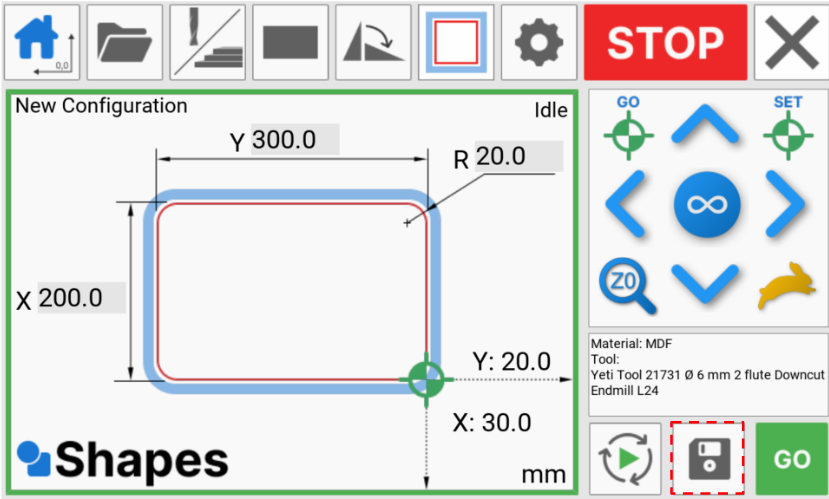
02 Interface
Shapes has been designed to use a simple workflow by working from the top left to bottom right hand corner

Key
Workflow functions
-
Home
-
Open configuration file
-
Material & tool selection
-
Select shape
-
Rotate shape
-
Toolpath offset
-
Setup
-
Stop
-
Exit application
-
Machine jog
-
Jog distance
-
Go to datum
-
Set datum
-
Probe Z axis
-
Jog speed
-
Material/ tool selected
-
Simulate job
-
Save configuration file
-
Run job

Canvas
-
Bumpers
-
Configuration name
-
Machine status
-
X dimension
-
Y dimension
-
Radius dimension
-
Datum position
-
Machine coordinates
-
Units
Home

The homing button can be used to home SmartBench, and to position the Z head to indicate sheet alignment to the machine.
This can also be used to re-home the machine in the event of a stall in an axis.
You can learn more about homing SmartBench here
Configuration files

This button allows you to open a previously saved configuration file.
The purpose of a configuration file is to capture all the parameters for a job, so that it can be quickly repeated at a later time.
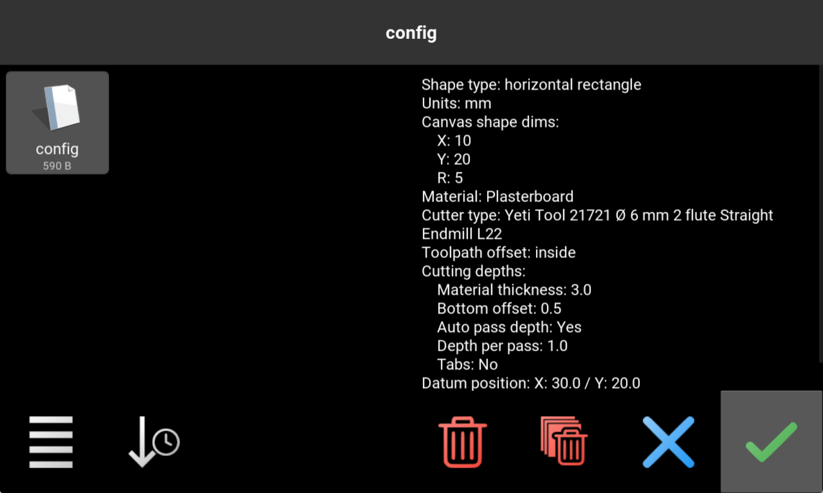
The configuration file contains the following (see later sections for definition):
These details can be found for each shape in the pane on the right handside
Deleting configuration files
From this window, we can also delete single or all configuration files.
To delete a single file, select the file and then press the delete button

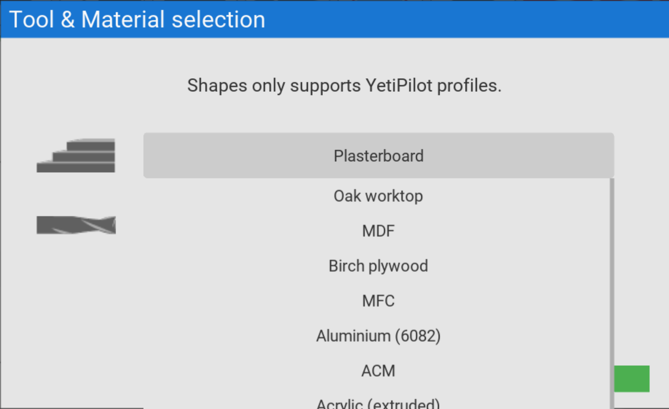
Material & Tool selection

The Material/ Tool selection button is used for selecting the material and tool for your job.
In Shapes V1.0, we will only support materials and tools which have YetiPilot profiles associated with them. This means, as a user, you do not need to input specific cutting parameters such as spindle speed and feed rates.
This also means that once you have selected the material, only the tools that are compatible with your choice will display in the tools section.
All of the tooling listed has been fully tested with SmartBench to give you the best output while being accurate and fast. You can purchase the tools from one of our trusted partners or directly through our website.
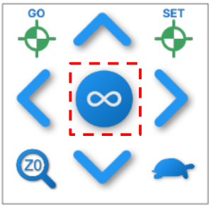
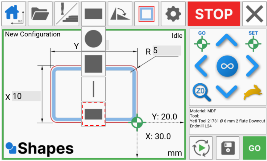
Select shape

The select Shape button changes the shape on the canvas.
Shapes supports a number of basic geometries including:
-
Squares
-
Rectangles
-
Circles
-
Straight lines
In addition to this, there is the option to add a radius to squares and rectangles.
Rotate shape

Shapes can be rotated at intervals of 90 degrees if applicable to that geometry.
Toolpath offset
Shapes supports 4 different toolpath offsets which are detailed below:
Inside

This cuts on the inside line of the dimensioned shape
Outside

This cuts on the outside line of the dimensioned shape
On-line

This cuts on the lien of the dimensioned shape
Pocket

This removes all of the material within the dimensioned shape
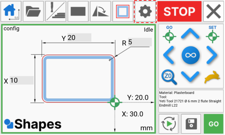
Setup

The setup button opens the setup dialogue to define parameters for your job including cutting depths and tabs.

Material thickness
This is where you specify the thickness of your stock material overall.

Bottom offset
Here, you can specify an offset from the bottom of your material. Entering a positive number here will increase the total cut depth, and using a negative number will decrease it.
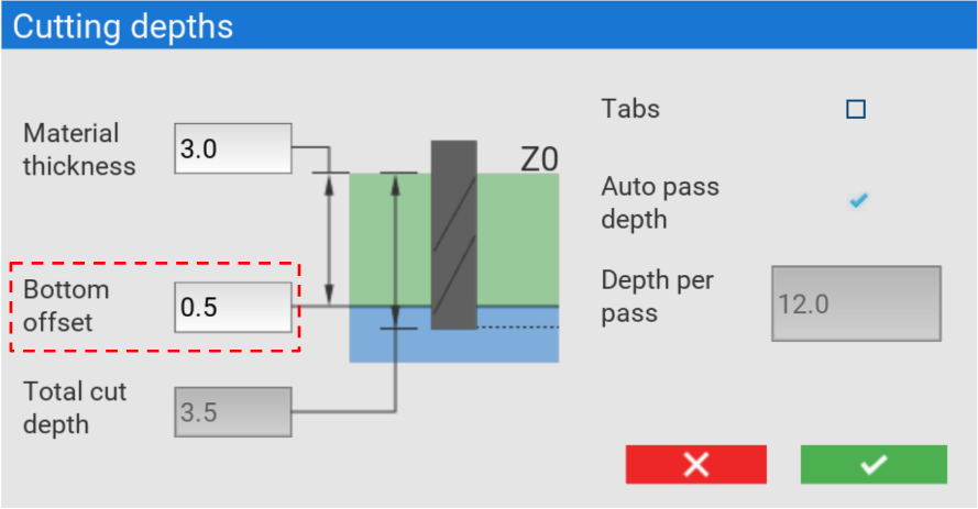
Total cut depth
The total cut depth is calculated by adding the material thickness and bottom offset together.

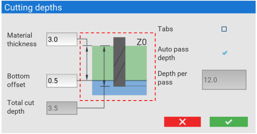
Depth widget
The cutting depth widget will update based on your input
Stop

The Stop button cancels any machine movements.
Exit

This button exits the Shapes app and returns to the YetiCut lobby.
Machine jog
These buttons can be used to jog the machine in the X and Y axis
Jog distance
Cycling through this button changes the jog distance of the machine
Go to datum

When flashing, this button sends the machine to the saved datum position
Set datum
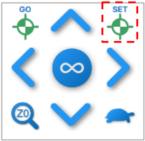
This sets the datum position on your machine
Probe Z axis
This starts the rapid Z probing function to set the height of your tool to the stock material.
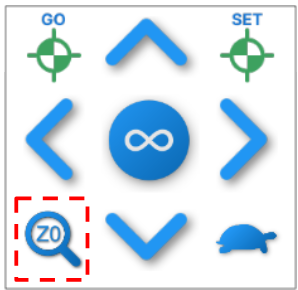
Before pressing this button, you must first remove the probe plate from its holder, and place it flat on the top of your stock material.
Once the probe button has been pressed
Jog speed

The jog speed can be toggled between slow or fast which effects the X and Y axis movement speed
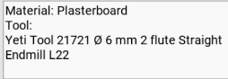
Material/ tool selected
This container displays which material and tool your currently have selected
Simulate job

This button allows you to simulate your job in air before running it.
Save configuration file

You can use this button to save your configuration file to be repeated again
Run job

You can press this button to run your job
Canvas

Bumpers
The Bumpers around the outside of the canvas indicate whether a job is in (green) or out (red) of bounds of the machine's working area.
Configuration name
The name of the current open configuration.
Machine status
Shows the status of SmartBench
X dimension
Allows you to input the X dimension of the shape
Y dimension
Allows you to input the Y dimension of the shape
Radius dimension
Allows you to input the radius dimension of the shape
Diameter dimension
Allows you to input the diameter dimensions of the shape
Datum position
Shows the datum position used for your chosen shape
Machine position
This shows the machine position values in X and Y based upon your sheet zero coordinates
Units
This shows the units used for the shape dimensions and machine position
Using Shapes
Example: For this example, we will be cutting a rectangle with radius corners, in some MDF.
Homing
When using the Shapes app for the first time after turning the machine on, we would recommend homing the machine.
This will ensure the machine knows its position, and at the end of the homing procedure, the laser (if fitted) or tool will point to where to align the corner of your sheet material to allow you to position and process a whole sheet.
If your laser has not been calibrated, you can find more information on how to do this here
Cutting a new configuration
This example will take you through starting a new job from start to finish.
Once you have homed the machine, you can select the material and tool we are going to use.
For this example, we are going to use MDF and the Yeti Tool - 6mm dia. 2 Flute Compression FL 22mm (4+18mm)
Press the Material and tool button to open the window
Now select the material from the drop down
We can now select our tool.

Because we have chosen a compression cutter, you will see an information reminder that this will add a lead-in to the toolpath automatically.
For more information on how this works, please see our section about lead-ins
It’s now a good time to load your chosen tool into your spindle motor. Information on removing the spindle motor and changing tools can be found here.
Now that we have the correct tool loaded, We can select the geometry we want to cut.
For this example, we are going to cut a rectangle with radius corners.
Select the shape button

And press rectangle
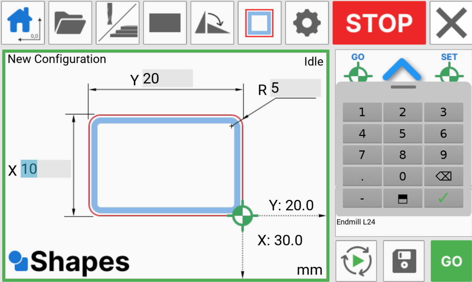
We can now input the dimensions of our shape.
Click on the input boxes to bring up the numpad. We can now type in the values for the X and Y axis.
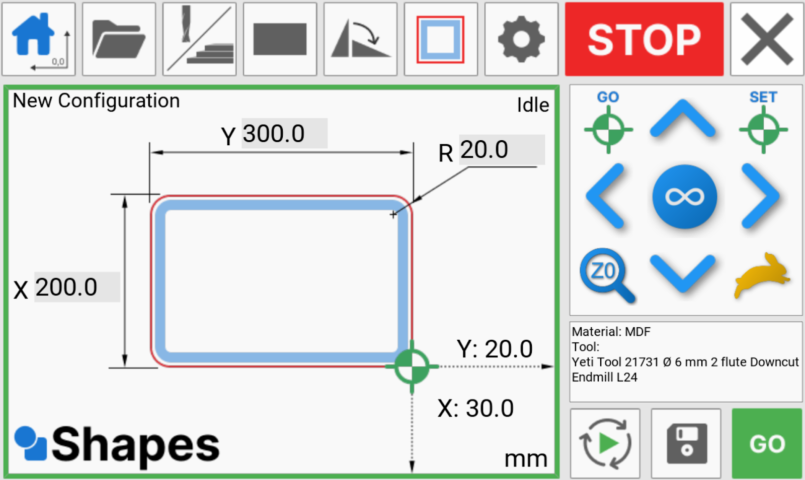
For this example, we will create a 200mm x 300mm rectangle with a corner radius of 20mm
If you wish, you can now rotate the shape.
I can now choose my toolpath offset for my shape. We would like to cut outside the line, meaning the part that we remove from the stock will be 200mm x 300mm.

The next step is to input some cutting parameters. Press the settings button to open the pop-up.
The material we are cutting is 12 mm thick, so we can put 12mm in the material thickness box
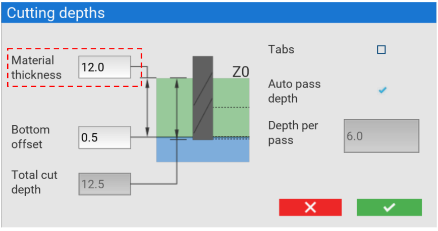
As our material will have some variance in thickness, we will tell SmartBench to cut an additional 0.5mm bottom offset in the Z axis to make sure we cut all the way through.

You can see that the total cut depth has been calculated for us automatically. This job will cut to a depth of 12.5mm
We can now decide if we would like to add tabs to our toolpath. Ticking the box will mean that tabs are automatically calculated. You can find out more about tabs here.
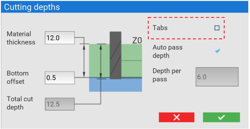
Pass depths can either be entered manually, or you can select Auto pass depth that will calculate the number of passes based on the parameters of the tool.
Next we need to position our job on our stock. To do this, we are going to jog the machine using the arrows. We are using the laser crosshair (if fitted) to position our job.
We can use the X and Y machine position values in the bottom right of the canvas to determine a more accurate position from our sheet 0,0.
Once we are happy with the position, we can press the SET button.

The simulate feature allows us to check that our job is position correctly on the machine. To do this, the machine drops the tool to within 5mm of the top surface of the material, and follows an outline of the shape in air.

When we are happy, we can save the configuration file
We are now ready to press the GO button
Cutting an existing configuration
For repeat jobs, you can cut from an existing configuration files.
To see what parameters are saved in a configuration file, please see here.
Open the configuration file
To open the configuration file, press the button to open the file chooser.
We can now select the file we want to use, and press the blue tick to confirm
Finishing passes
Shapes automatically adds finishing passes to your toolpaths if applicable to the chosen shape/ offset combination
Tabs
Tabs can be added to your geometry to ensure your part doesn't come loose when cutting.
Tabs can be enabled in the material setup popup. If the perimeter of your shape is large enough, shapes will add 3D tabs at a consistent distance along the edge of your toolpath.
Tabs are not available for pocketing operations.
Lead-ins
When using compression cutters, it’s important to use lead-ins to ensure the downcut portion of the tool is in contact with the top surface of the material to minimise breakout.
We add lead-ins automatically for you when a compression tool is selected but only for certain geometry and toolpath offset combinations.
If cutting inside the line, we will add a lead-in of 10mm on the inside of the toolpath. And likewise, if you are cutting outside the line, we will add a lead-in of 10mm on the outside of the toolpath.
Lead-ins are not required on pocket cuts, as we start a pocket cut from the inside of a shape and work outwards.
Error messages
Shapes will display the following error messages should you attempt to cut:
1. In case where the R input is greater than the smaller side of the shape:
The radius value is too large.
Try reducing the 'R' input.
2. In case where a side of a square is smaller than the tool's diameter (or 0.1 depending on tool path offset)
The square is too small.
Try increasing the 'Y' input.
3. In case where a side of a rectangle is smaller than the tool's diameter (or 0.1 depending on tool path offset)
The rectangle's sides are too small.
Try increasing the 'X' and 'Y' inputs.
4. In case where a circle's diameter is smaller than the tool's diameter (or 0.1 depending on tool path offset)
The circle's diameter is too small.
Try increasing the 'D' input.
5. In case where a line is less than 0.1 long
The line is too small.
Try increasing the 'L' input.
6. In case material thickness is less than 0
Material thickness cannot be negative.
Try increasing the material thickness.
7. In case where bottom offset is negative and larger (in magnitude) than material thickness
Bottom offset cannot be greater than material thickness
Try reducing the bottom offset, or increasing the material thickness.
8. In case where total cut depth is less than 0
Total cut depth cannot be negative
Try reducing the bottom offset, or increasing the material thickness.
9. In case where total cut depth exceeds soft limit for cut depth
Total cut depth exceeds 62mm
Try increasing the bottom offset, or reducing the material thickness.
10. In case where total cut depth doesn't equal material thickness + bottom offset (shouldn't be customer facing, but it is a check we do)
Total cut depth must be equal to material thickness + bottom offset.
11. In case where depth per pass is greater than the max cut depth per pass for the tool
Depth per pass exceeds max depth per pass for this tool.
Try reducing the depth per pass, or use a different tool.
12. In case where depth per pass is less than or equal to 0
Depth per pass must be positive.
Try increasing the depth per pass, or use auto pass.
13. In case where cut depth exceeds cutter flute length
Cutting depth exceeds cutter flute length.
Try reducing cut depth, or use a different tool.