This article will explain the procedure to service your X axis wheels.
< Previous | List |
Wheel setting rules and procedures
Tools required
You will need the following tools for repair/maintenance:
A: T25 torx
B: Wheel adjustment spanner

Understand how to adjust wheels
|

|
Make sure the wheels are loose. To do this, loosen the M5 torx screw with a T25 torx tool so the position can be changed.
|
In general, to adjust wheel position, hold the position of the M5 screws with a T25 torx tool and use a wheel adjuster spanner to change the position of the wheel.
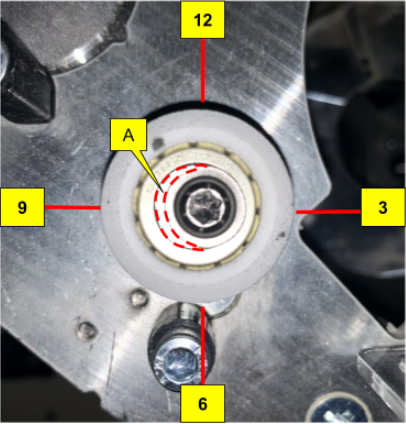
Here we will use the analogy of a 12-hour clock to describe the wheel position. For example the image below shows the change of wheel position from 9 o’clock to 12 o’clock.
The reference mark (A) describes the position of the wheel, initially it's positioned at 9 o’clock.
A: Reference mark for wheel position

After rotation, the position changed from 9 to 12 o’clock.

Here is another demonstration on how to do this on the Z Head.
|

|
As there is no actual arrow marked on the wheel. The centre of the region enclosed by “A” (or the imaginary centre arrow of “A”) has to approximately match the respective outer position (here we are defining .
|
A: Reference mark for wheel position
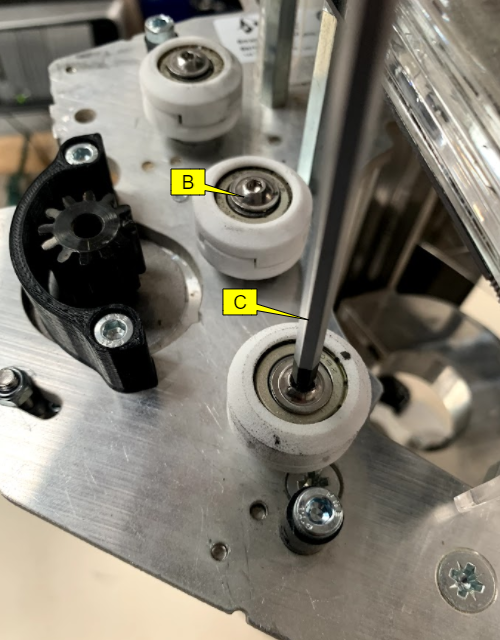
If not already, slacken the M5 torx screw by using a T25 torx tool.
B: M5 torx screw
C:T25 torx tool
Fit the wheel adjustment spanner to the bearing adjuster as shown in the image.
D: Wheel adjustment spanner
E: Bearing adjuster

Hold the position of the T25 torx tool and only rotate the wheel adjustment spanner.
F:T25 torx tool
G: Wheel adjustment spanner
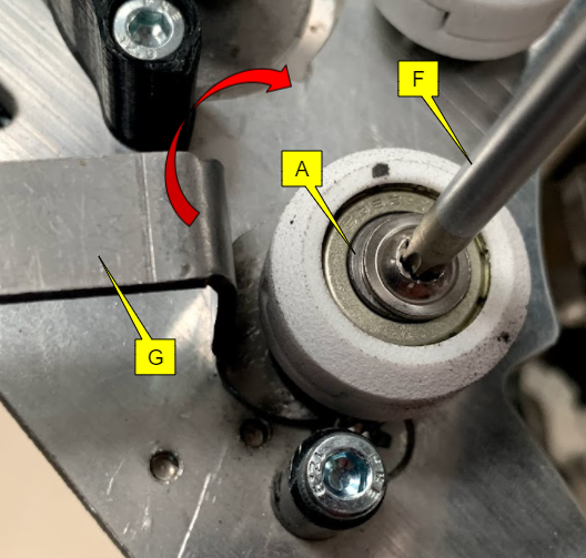
By rotating the wheel adjustment spanner only you can change the position of the wheel, for example, we have gone from 9 o’clock to 12 o’clock (by rotating clockwise).
F:T25 torx tool
G: Wheel adjustment spanner

Once you are happy with the position of your wheel, tighten the M5 torx screw with a T25 torx tool and this time hold the position of the wheel adjustment spanner to lock the wheel in position.
F:T25 torx tool
G: Wheel adjustment spanner
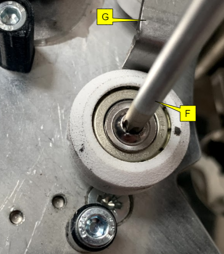
This is how the position of the wheel looks at 12 o’clock
A: Reference mark for wheel position

|

|
Use the above ideology to change the wheel position.
|
Step 1: Setting the initial wheel position
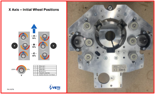
Use the initial wheel setting card to position the wheel as shown in the image. In this card you will also find links and QR codes to our knowledgebase where you will find the relevant articles and videos. Also make yourself aware of the safety data for the loctite used.
|

|
When setting X wheels, always start with this chart and position your wheels accordingly.
|

We have also given an identity to the wheels, for example, 1st row wheels are called wheelset one, 2nd row wheels are called wheelset two, etc.
|

|
Whenever you set your wheels make sure to set Z Head orientation with respect to the direction shown in the card above.
|
Check the Z Head fitting
Before loading the wheels make sure the motor pinions are not engaged with the racks as was discussed in the Z Head preparation article

Once you have set the initial wheel positions do the following:

|

|
For decreasing the preload rotate wheelset 1 clockwise.
And recheck the fitting, you can continue decreasing the preloading until the Z Head enters the rail.
|
|

|
For increasing the preload rotate wheelset 1 anti-clockwise.
And recheck the fitting, you can continue increasing the preloading until there are no loose wheels.
|
An example to check wheel set 1 for looseness:
To check wheelset 1, bring the Z Head closer to the console and check both sides of the wheels. If wheels spin freely then they are not touching the rails and are loose.
|

|
If the wheel spins with your finger then gradually increase the preload on both the wheels and recheck the fitting.
|

Step 2: Set preload on wheel set 1
Change the wheel position on wheel set 1 as highlighted in the image and ensure that both sides are symmetry and have an equal amount of preload
H: Wheelset 1
|

|
The preloading shown in the image is an approximation, after which you can decide whether to add or reduce preload while testing on the bench.
|

Step 3: Set preload on wheel set 2
Change the wheel position on wheel set 2 as highlighted in the image and ensure that both sides are symmetry and have an equal amount of preload
I: Wheelset 2
|

|
Do not change the setting on wheel set 1.
|
|

|
The preloading shown in the image is an approximation, after which you can decide whether to add or reduce preload while testing on the bench.
|

Once you have set the preload on the wheels check the Z Head fitting for the following:

|

|
For decreasing the preload rotate wheelset 2 clockwise.
And recheck the fitting, you can continue decreasing the preloading until the Z Head enters the rail.
|
|

|
For increasing the preload rotate wheelset 2 anti-clockwise.
And recheck the fitting, you can continue increasing the preloading until there are no loose wheels.
|
An example to check wheel set 2 for looseness:
To check wheel set 2, bring the Z Head to the far end of the Upper X Beam and make sure wheel set 3 is not inserted in the rail. Check both sides of the wheels if wheels spin freely then they are not touching the rails and are loose.
|

|
If the wheel spins with your finger then gradually increase the preload on both the wheels and recheck the fitting.
|
I: Wheel set 2
J: Wheel set 3

Step 4: Set preload on wheel set 3
Change the wheel position on wheelset 3 as highlighted in the image and ensure that both sides are symmetry and have an equal amount of preload i.e. rotate the left side wheel to 1 o’clock position and the right side wheel to 7 o’clock position.
J: Wheelset 3
|

|
Do not change the setting on wheel set 1 & 2.
|
|

|
The preloading shown in the image is an approximation, after which you can decide whether to add or reduce preload while testing on the bench.
|

Once you have set the preload on the wheels check the Z Head fitting for the following:

|

|
For decreasing the preload rotate wheelset 3 clockwise.
And recheck the fitting, you can continue decreasing the preloading until the Z Head enters the rail.
|
|

|
For increasing the preload rotate wheelset 3 anti-clockwise.
And recheck the fitting, you can continue increasing the preloading until there are no loose wheels.
|
An example to check wheel set 3 for looseness:
To check wheel set 3, bring the Z Head to the far end of the Upper X Beam and make sure wheel set 3 is fully inserted in the rail. Check both sides of the wheels if wheels spin freely then they are not touching the rails and are loose.
|

|
If the wheel spins with your finger then gradually increase the preload on both the wheels and recheck the fitting.
|

Step 5: Lock the motor in position
Once you have finished setting the wheels, you will need to rotate the pinions back into the racks.
Rotate the motor pinions on both sides of the Z Head to mesh with the racks.
K: Z Head motor
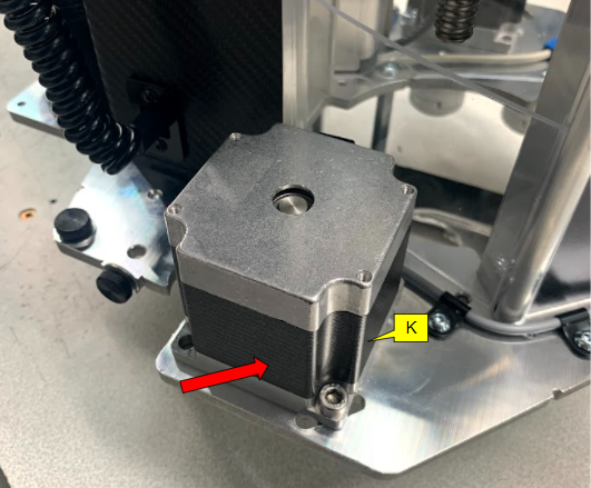
Tighten off the 4mm hex socket at the top of the motor on both sides of the Z Head.

And also tighten the hex bolt by using a 4mm torx driver and 8mm spanner and repeat the same step on other sides of the Z Head motor.
L: 4mm torx driver
M: 8 mm spanner

Step 6: After procedure checklist
Once you are happy with the setting of the Z Head do the following:
|

|
If you need any assistance with the wheel replacement process then submit a support ticket by clicking here.
|