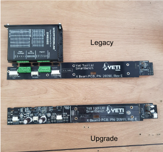
This will upgrade your lower beam from a Stepper “Brick” connected to a PCB, to an all in one integrated stepper driver PCB.
Legacy Lower Beam Upgrade Process, this article is an installation guide for the upgrade part sold here
Before you start
|

|
Disconnect the lower beam from SmartBench and remove all power cables.
|
Start by removing the Lower X Beam assembly from SmartBench.
Check contents
|
E-stop button
|
2.5mm Hex Driver
|
|
Trinamic X Beam version 3 PCB
|
3mm Hex Driver
|
|
6x Grey blanking plugs
|
7mm Nut Spinner
|
|
4 x M4 x16mm
|
Side Cutters
|
|
1x Zip Tie
|
New power supply unit and PCB cover
|
|
2x M3 x 6mm button head bolts
|
|
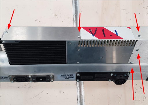
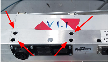
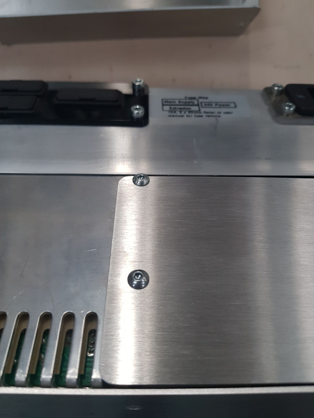
Step 1 - Remove the PSU cover
Remove the 4x M4x8mm bolts on the top side of the case with the 3mm hex driver.

Remove the remaining 5x M3x6mm bolts using the 2.5mm hex driver.
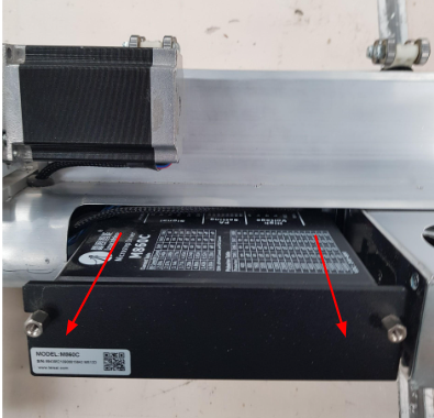
Step 2 - Remove the stepper brick
Remove the stepper brick by pulling it towards you. This is a push fit connection.
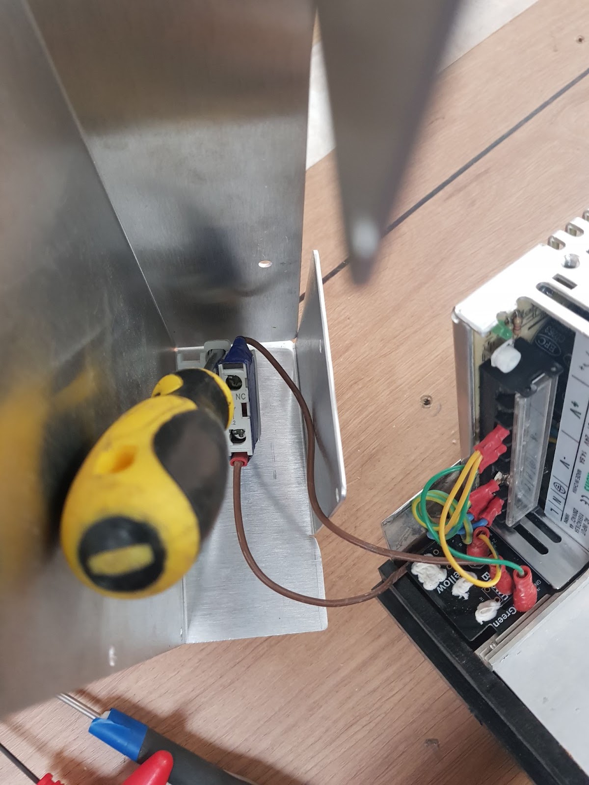
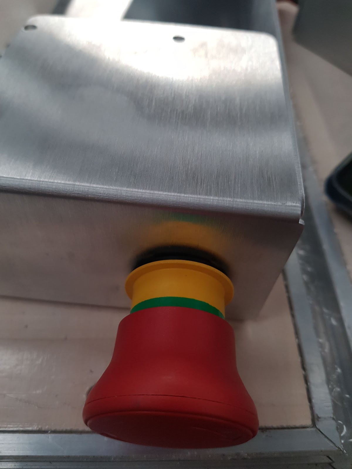
Step 2a - Remove E-stop button
Using a flat screwdriver, insert it into the tab on the rear of the switch and gently lever it towards you. The connector will pull away from the casing.

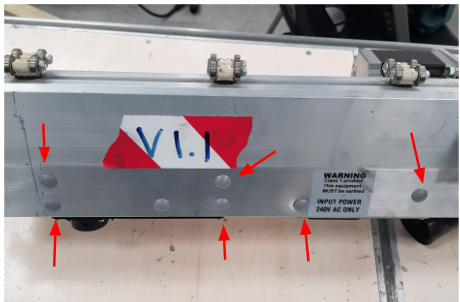
Step 3 - Remove the plastic caps
Remove the 6x plastic caps. They are easy to lift off with a flat blade screwdriver taking care not to scratch the aluminium. We have included some new caps, so do not worry if you damage them when removing them.
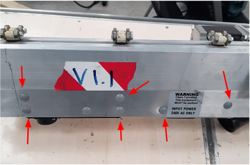
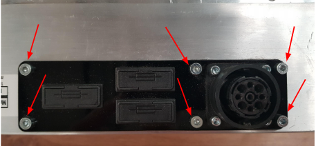
Step 4 - Remove the fuse plate
Remove the electrical fitting by removing the 6x M4x8mm bolts.

Step 4a - Unbolt the PSU
Remove the 4x M4x14mm bolts which secure the power supply unit in place with the 3mm driver.
Step 5 - Unplug looms
Cut the cable ties holding each of the looms in place.Be very careful not to damage the wiring.
Step 6 - Unbolt the PCB
Remove the 2x M4x12mm bolts with a 3mm driver which hold on the PCB, these are held on with 2x 7mm nuts on the rear and use the 7mm nut spinner to keep these in place while removing the bolts.
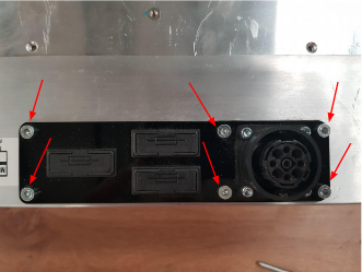
Step 7 - Unplug front face PCB connections
Remove the three plugs on the front face of the PCB. You may need to use a pair of pliers.
Step 7a - Unplug back face connectors
Remove the two plugs and the connector on the rear of the PCB.
Step 8 - Fitting the new PCB
|

|
The acrylic PCB and power supply spacers are no longer required when fitting the new board; they are both integrated.
|
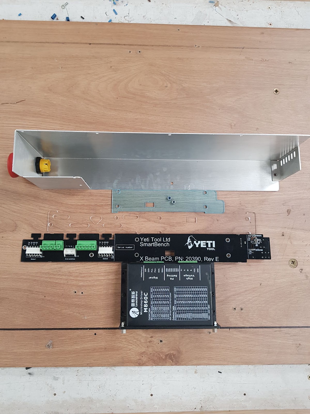
Fit the new PCB into place attaching the plugs on the back and front. The metal heatsink is on the back of the new PCB for reference.
|
|
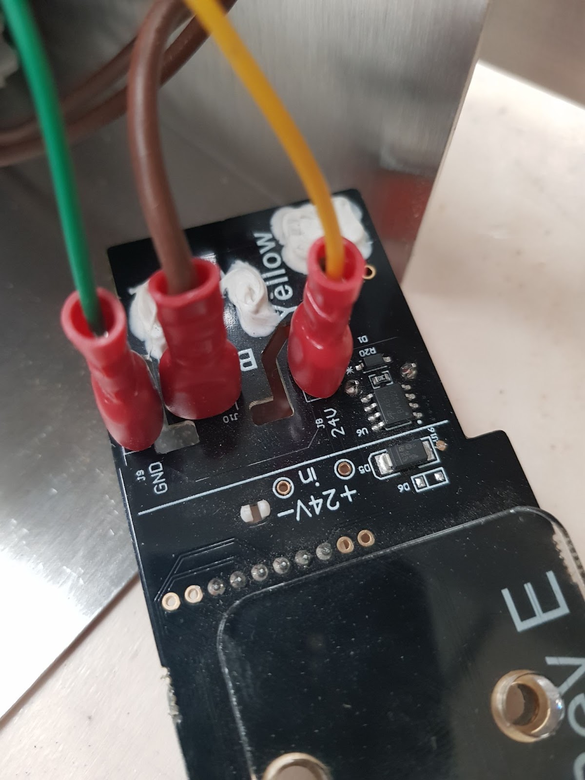
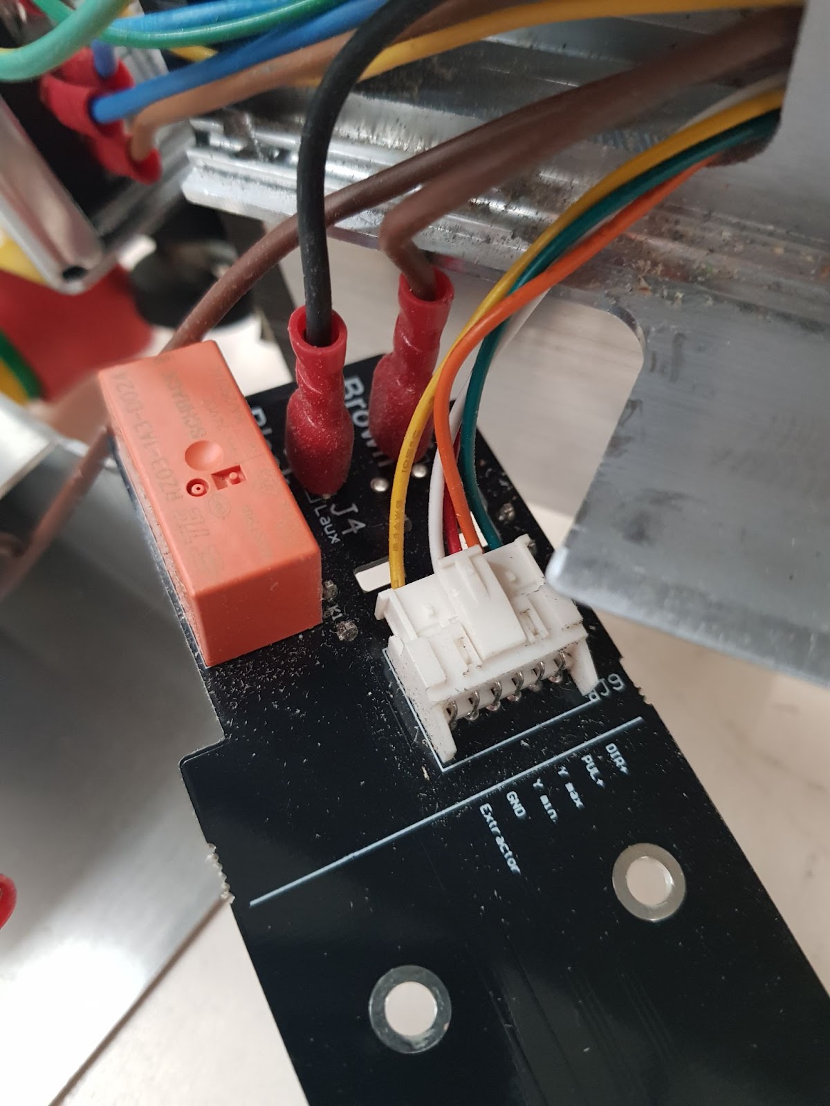
The wires should be routed in the gap next to the Green Yellow and Brown crimps on the front face of the PCB to prevent them being trapped
|
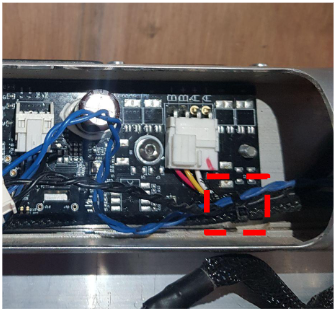
Step 9 - Cut the motor connectors
Cut the two motor connectors where there are two missing pins as per the below photo. Do not cut into any of the existing pins or into the housing of those pins.. Connect the motor connectors up again after the cut.
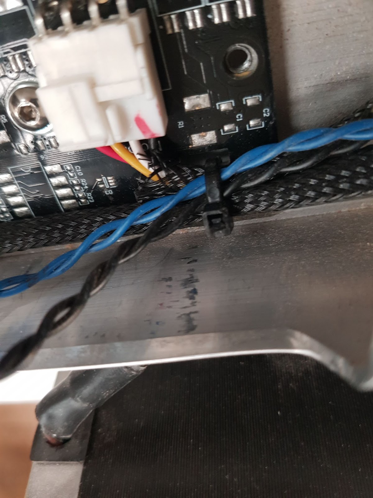
Step 10 - Strain relief cables
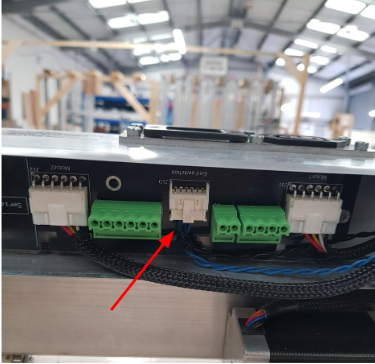
After connecting the cut motor cables to their original positions and plugging in the limit switch connector
Use the cable tie to keep all of the cables together as shown below.
Step 11 - Attach the new PCB
Attach the PCB to the lower beam using the 2x M4x12mm bolts from step 6 but from the rear instead.
|
|
Do not attach the nut again, it is no longer needed and may damage the board.
|

Step 12 - Fit the PSU
Offer up the PSU to the lower beam and fix in place with the 4x M4x16mm bolts supplied with the 3mm hex driver. (The existing M4x14mm bolts are difficult to fit hence why we recommend these slightly longer M4x16’s) Do not include the acrylic spacer as this is now attached to the PCB.
|
|
Be careful not to pinch any wires when fitting the bolts. It is good to carry out a visual check here while the fuse plate is detached.
|
After this is done reconnect the fuse plate holder with the 6x M4x8mm bolts
Step 13 - Attach the E-stop
Attach the new E-stop button supplied to the new PSU cover. Align the yellow tab with the notch in the cover, push fit firmly and then screw on the retaining nut to the rear.


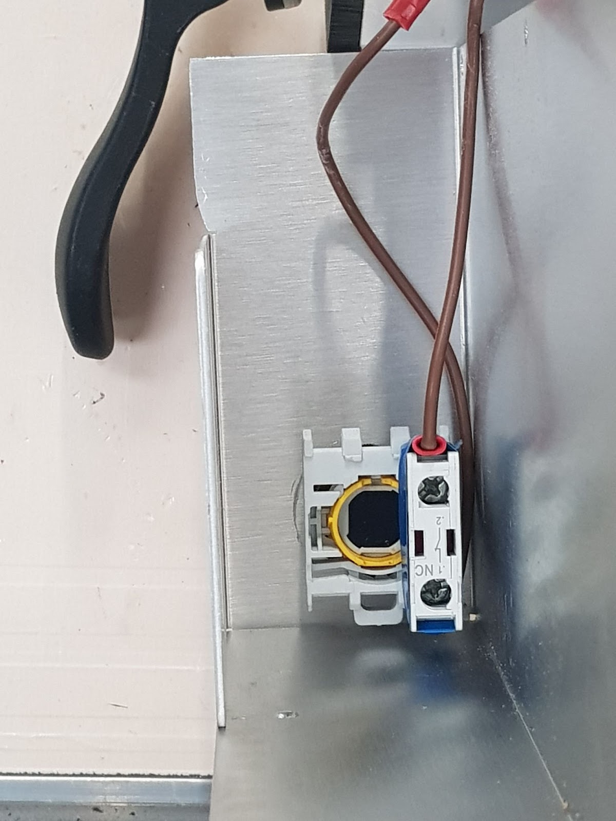
Step 13a - Attach E-stop rear
Attach the E-stop button connector This is just a push click fitting. The orientation is important here.
Step 14 - Fit PSU cover
Reattach the new PSU cover. We have included 2x new M3 x 6mm bolts for the additional fixing positions below.
Step 15 - Fit lugs
Reinstall the back grey lugs. We include replacement ones just in case the old ones are damaged.
Step 16 - Change the settings
|
|
Note the trinamic PCB uses a slightly different driver chip, which will sound and behave slightly differently to the previous version.
|
The motor pin direction on the newer lower beam board has been swapped, this will need to be adjusted for in the console settings
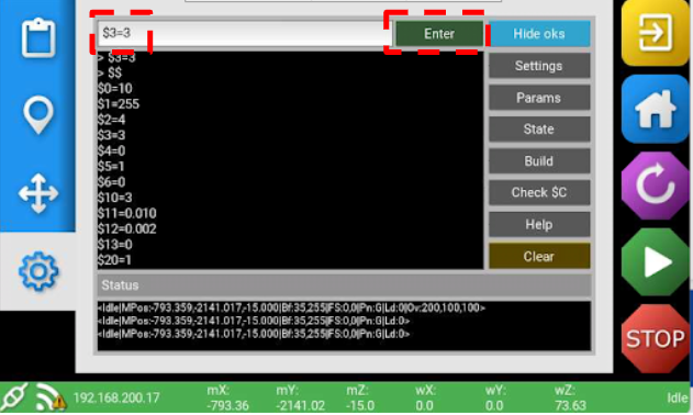
To set your new upgraded board going the correct way with your older motors you will need to change one setting. This is the $3 setting, it needs to be changed to equal 3 instead of 1.
*Skip the homing procedure* - With the red X in the top right corner

Step 16a
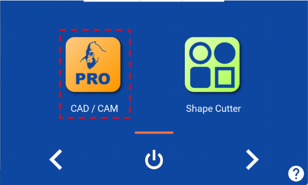
Navigate to the Pro CAD/CAM application on the console.
Step 16b
Press the gear icon to enter the GRBL settings
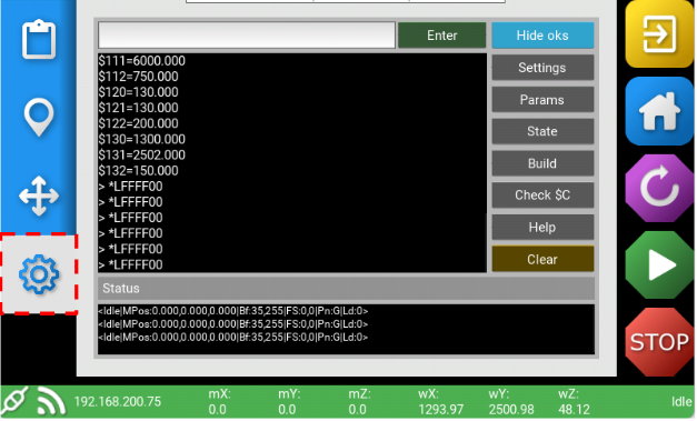
Step 16c
Press the white field at the top to bring up the keyboard. Enter the following without spaces
$3=3
Press the green enter button
Step 16d
You will see a pop up with a warning, press ok
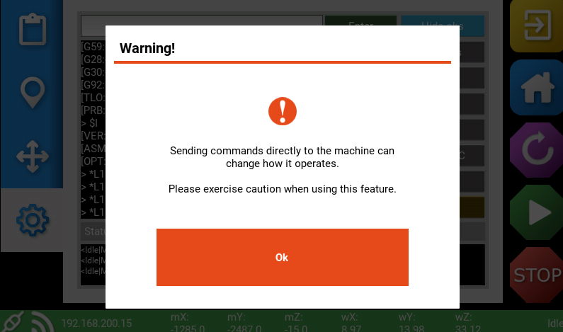
Then press the green enter button again - this will actually set it.

Press the grey settings button on the right to reload everything.

You are now able to ensure the settings are correctly set by scrolling through the dollar settings. Ensure $3=3 and not the original $3=1
If you still find movement direction issues the alternative is to try $3=7. This guide is complete
Support
If you have any issues or suggestions, please submit a support ticket