Replacing a failed Z axis limit switch
Before replacing the limit switches, it's highly recommended to check which version of the Z Head you are using. Click here to learn about SmartBench Z Head versions.
Components needed
For Z-Heads 1 and 2 the Z axis limit switch is accessed on the side of your Z-head and can be replaced here
|

|
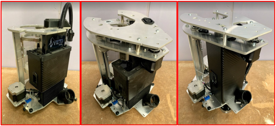
The instructions in this section onwards are for Z Head 2b and 3 only.
|
Opening the casing
|

|
Ensure you have plenty of space to lay out the components that will be removed from the Z Head before you start.
|
Start by removing the Z Head top plate.
R: Z Head top plate
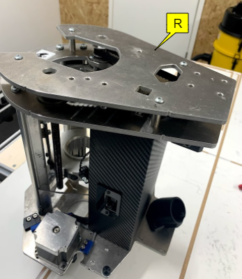
Use a 3mm allen key to remove all four screws.
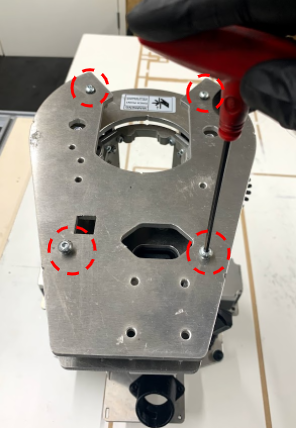
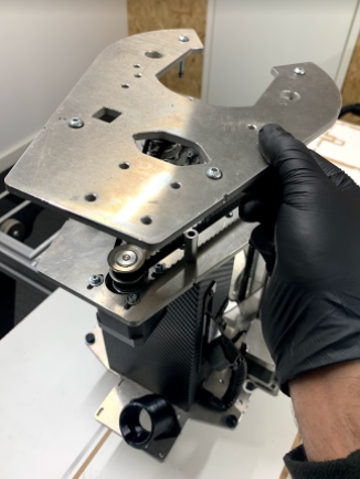
Once unscrewed, lift the top plate off the Z Head.
Pull off the four spacers highlighted in the image.
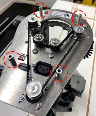
Next, we will remove the belt by first reducing the tension on the belt.
To reduce the tension, unscrew the four motor screws with the 2.5mm allen key.
S: Belt
T: Motor
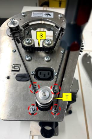
And push the motor all the way towards the casing. This will take out the tension on the belt.
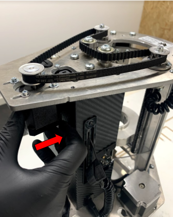
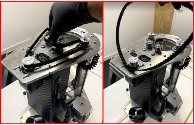
Now you can easily remove the belt as shown in the image.
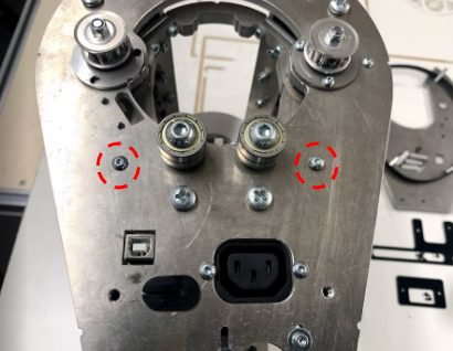
Unscrew the two screws which secure the top of the casing by using a 2mm allen key.
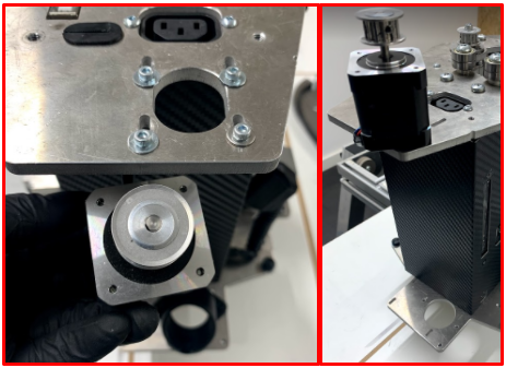
Fully unscrew the motor and remove it from the top of the casing and place the motor on top of the Z Head.
Remove the probe plate from the Z Head: unplug the probe plate connector, and then remove the probe plate from its housing.
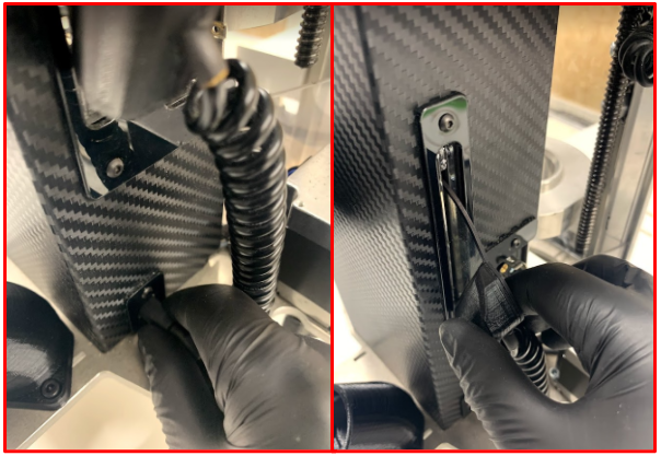
Remove the dust shield on the probe plate housing by using a 2mm allen key.
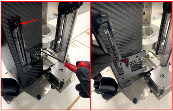
Remove the dust shield on the probe plate connection socket by using a 2mm allen key.
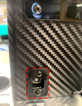
On the left hand side of the Z Head, remove the signal cable shield with a 2mm allen key.
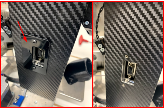
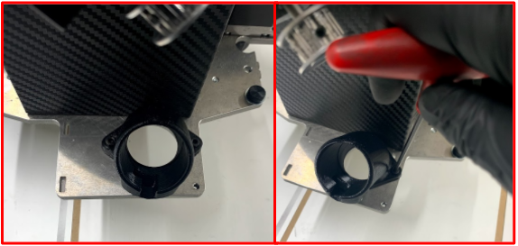
Remove the extraction elbow with a 2mm allen key.
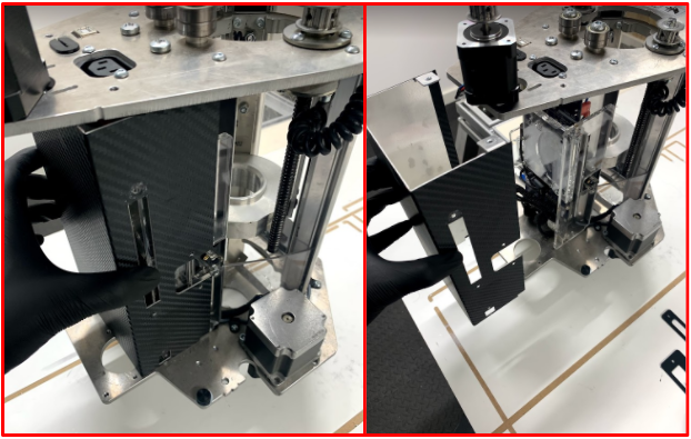
Pull the casing away from the Z Head.
Secure all the removed components in a safe place, as you will need to re-fitting them later!
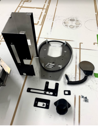
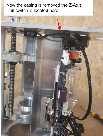
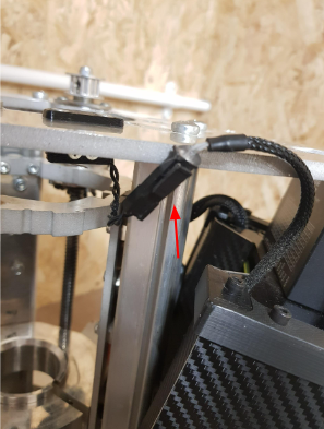
Now the full casing has been removed the Z-Axis switch can now be accessed for replacement
